Control board and Driver board interface
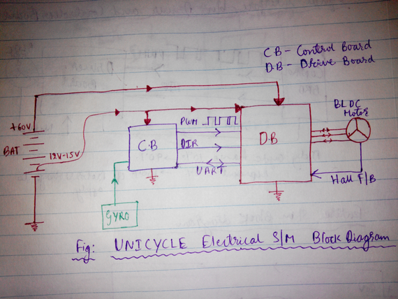
(Referring to the figure attached)
Functionality of each board in brief.
Control Board(CB):
> Reads the signal from the Gyro and calculates the voltage to be applied to the motor using closed loop control.
> Sends this voltage to the Driver board.
Driver Board(DB):
> Decodes the voltage value communicated by CB and applies it to the BLDC motor in the right direction.
The attached image shows the
>Power distribution and
>Signal Interface
between different components.
How should CB communicate with DB????
- The figure shows 2 ways to communicate.
1) PWM and Direction (DIR)
With these 2 lines CB can send voltage and Direction info to the drive.
> Voltage is sent in the form of PWM signal with Duty Cycle changing from 10% (0V to motor) and 90%(Max 60V to motor)
> Direction is sent in the form of binary for CW or CCW.
Pros:
-Less processing either side.
Cons:
-Only voltage and DIR can be communicated.
-Unidirectional
2) UART (Tx and Rx)
>Voltage and DIR info can also be sent using UART lines.
>Data needs to be packed in a particular format in CB and sent to DB.
Pros:
- Data can be bidirectional.
DB can send other data like Motor current and Error status of DB.
Cons:
- Adds processing delay in packing and decoding the data.(in both CB and DB)
- Serial communication itself will have the delay of sending data bit after bit.
So which is best for Volt and DIR communication??
>Among these shortlisted 2 options we need to choose anyone to start with based on some calculations and simplicity to implement.
-Though technically both are simple to implement PWM and DIR method will take less time to complete.
To get the benefit of PWM & DIR(METHOD -1) method over UART (METHOD -2) we need to select the appropriate PWM frequency.
Minimum of 1Khz has to maintained to gain the control loop effectiveness at 1Khz.
Comments